CBD forward model#
Experimental setup#
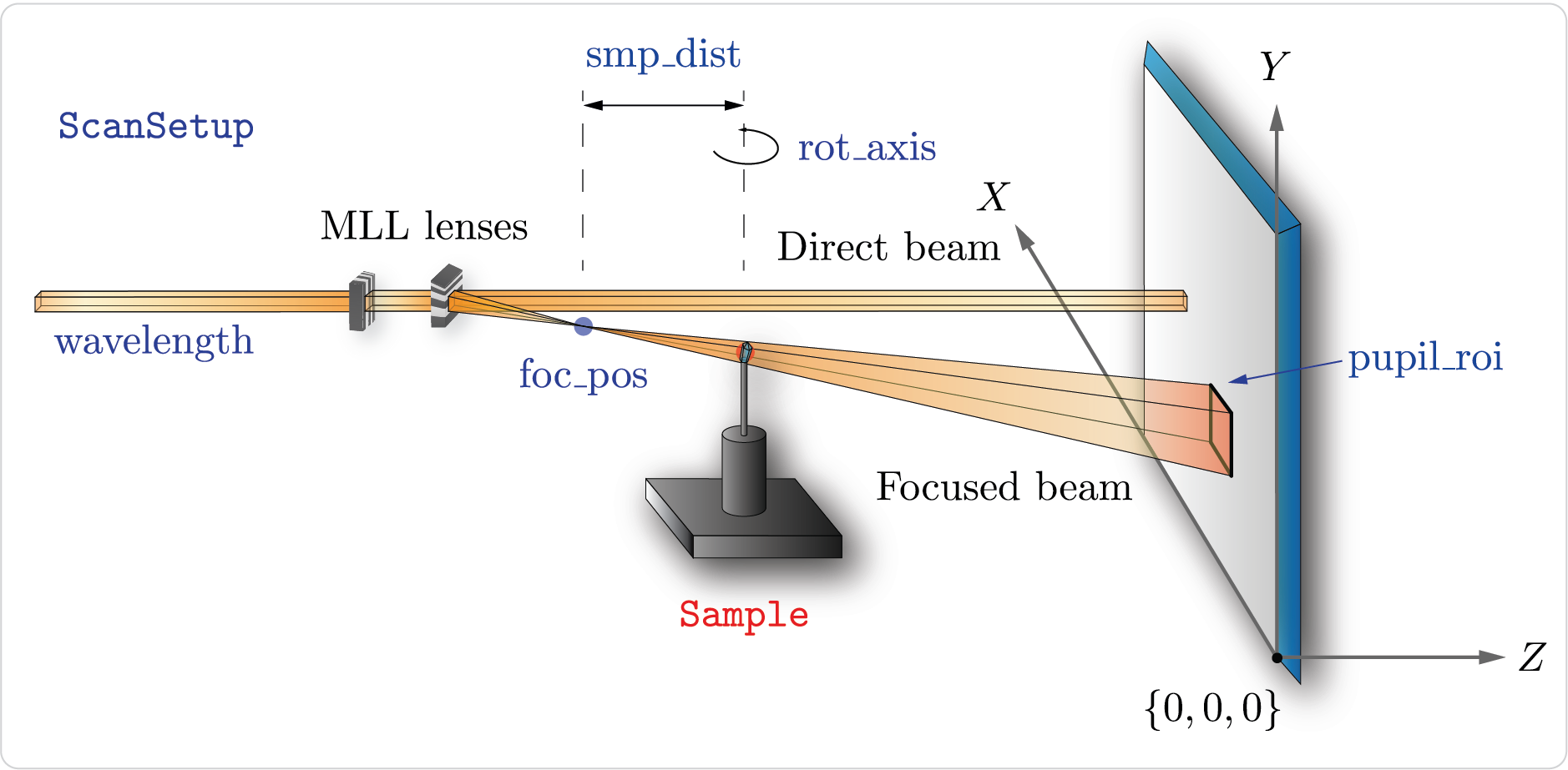
In the experimental setup of a CBC experiment a pair of lenses focuses the X-ray beam into a point and a crystalline sample is put in the X-ray beam at a ceratin
distance downstream. The sample diffracts the incoming X-ray beam into a diffraction pattern captured by the detector. The experimental geometry is stored in
cbclib.ScanSetup container, which comprises the following parameters:
foc_pos : Focal point of the incoming X-ray beam.
pupil_roi : Focus beam extent
[y_min, y_max, x_min, x_max]at the detector plane. Since the beam is formed by two 1D focusing lenses, the focused beam has a rectangular shape.rot_axis : The axis of sample rotation. The axis is defined by its azimuth and inclination.
smp_dist : Focus-to-sample distance in meters.
wavelength : The wavelength of the incident X-ray beam in meters.
x_pixel_size and y_pixel_size : Detector pixel size along the x and y axes in meters.
Note
All coordinates are defined relative to the origin of the detector and z axis is directed collinearly with the direction of X-ray beam propagation.
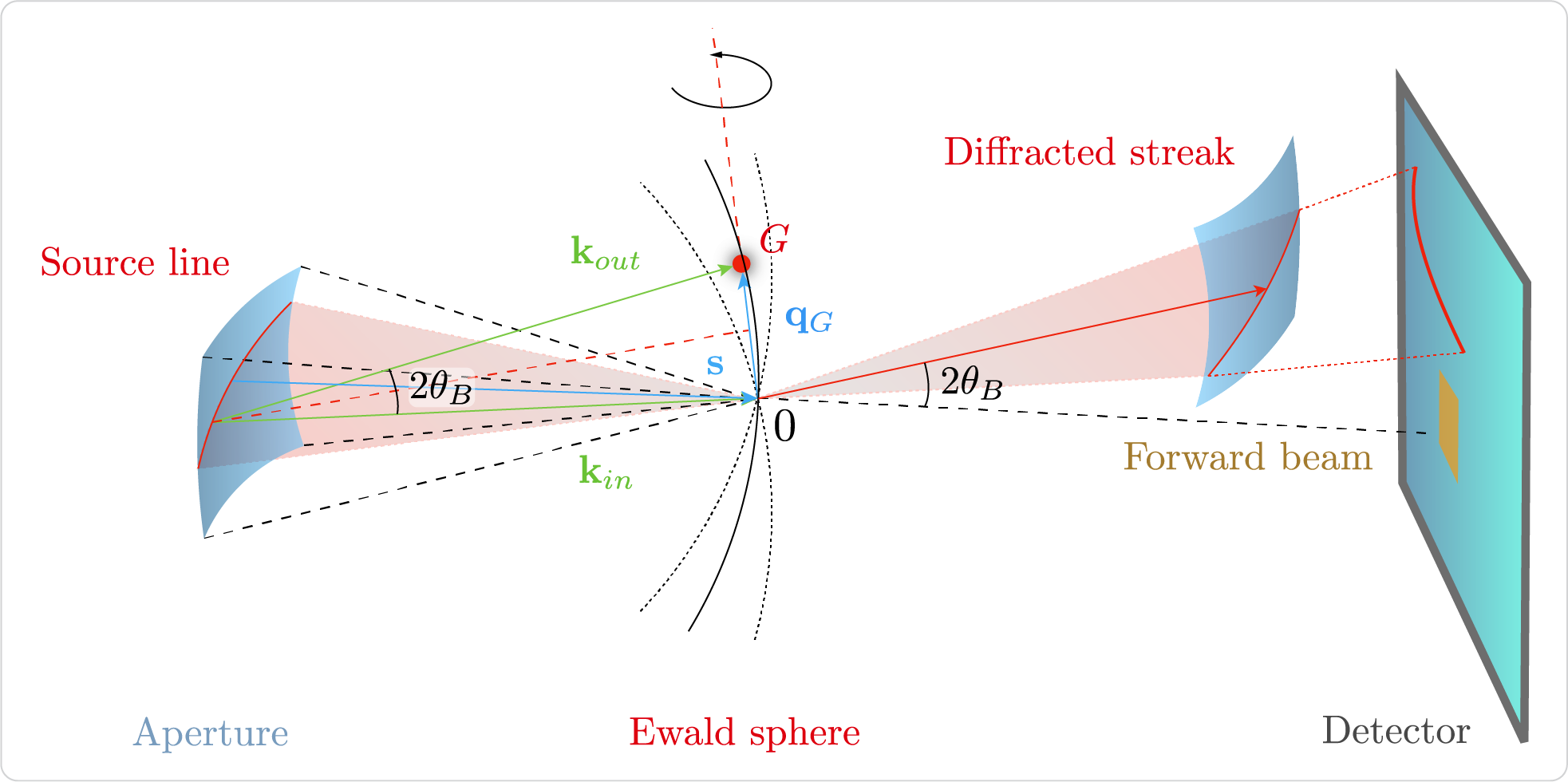
A location at the detector plane is related to a wave-field emanated from the source point \(\mathbf{x}_s\) inside the sample and scattered along the \(\mathbf{k}_{out}\) wave-vector as follows:
See also
cbclib.ScanSetup provides methods to project a detector point to a outcoming wave-vector (detector_to_kout)
and vice-versa (kout_to_detector) following the above equation.
The source point \(\mathbf{x}_s\) is assumed to lie at the sample plane and can be expressed as a function of the incoming wave-vector \(\mathbf{k}_{in}\):
See also
The above equation is used in cbclib.ScanSetup.kin_to_sample() to project an incident wave-vector to a source point at the sample plane.
CBDModel#
The forward model cbclib.CBDModel takes the following objects:
Basis : Reciprocal lattice unit cell vectors (
cbclib.Basis).Sample : Sample’s position and orientation (
cbclib.Sample).Setup : Experimental setup (
cbclib.ScanSetup).
cbclib.CBDModel finds all the coordinates on the detector that satisfy the Bragg condition for reflection (see generate_streaks)
and calculates the standard reflection profile \(f^2_{hkl}(\mathbf{x})\) (see pattern_dataframe). The location of a
reflection on the detector is defined by a set of incident wave-vectors that satisfy the Bragg condition. These incident wave-vectors are given by:
See also
cbclib.bin.calc_source_lines() takes a set of reciprocal lattice points and calculates the source lines following the above equation.